Welcome to ExtremeHW
Welcome to ExtremeHW, register to take part in our community, don't worry this is a simple FREE process that requires minimal information for you to signup.
Registered users can:
- Start new topics and reply to others.
- Show off your PC using our Rig Creator feature.
- Subscribe to topics and forums to get updates.
- Get your own profile page to customize.
- Send personal messages to other members.
- Take advantage of site exclusive features.
- Upgrade to Premium to unlock additional sites features.

mllrkllr88
-
Posts
43 -
Joined
-
Last visited
-
Days Won
6 -
Feedback
0%
Content Type
Forums
Store
Events
Gallery
Profiles
Videos
Marketplace
Tutorials
Everything posted by mllrkllr88
-

"Second star to the right, and straight on till morning."
mllrkllr88 replied to ENTERPRISE's topic in Announcements
I am really sad to see you go; it's been a nice journey with you. I wish you the best of luck with your future endeavors. -
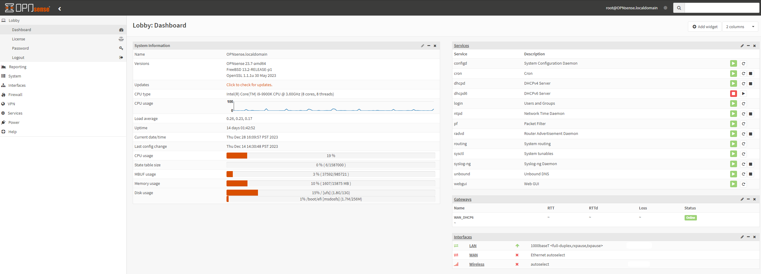
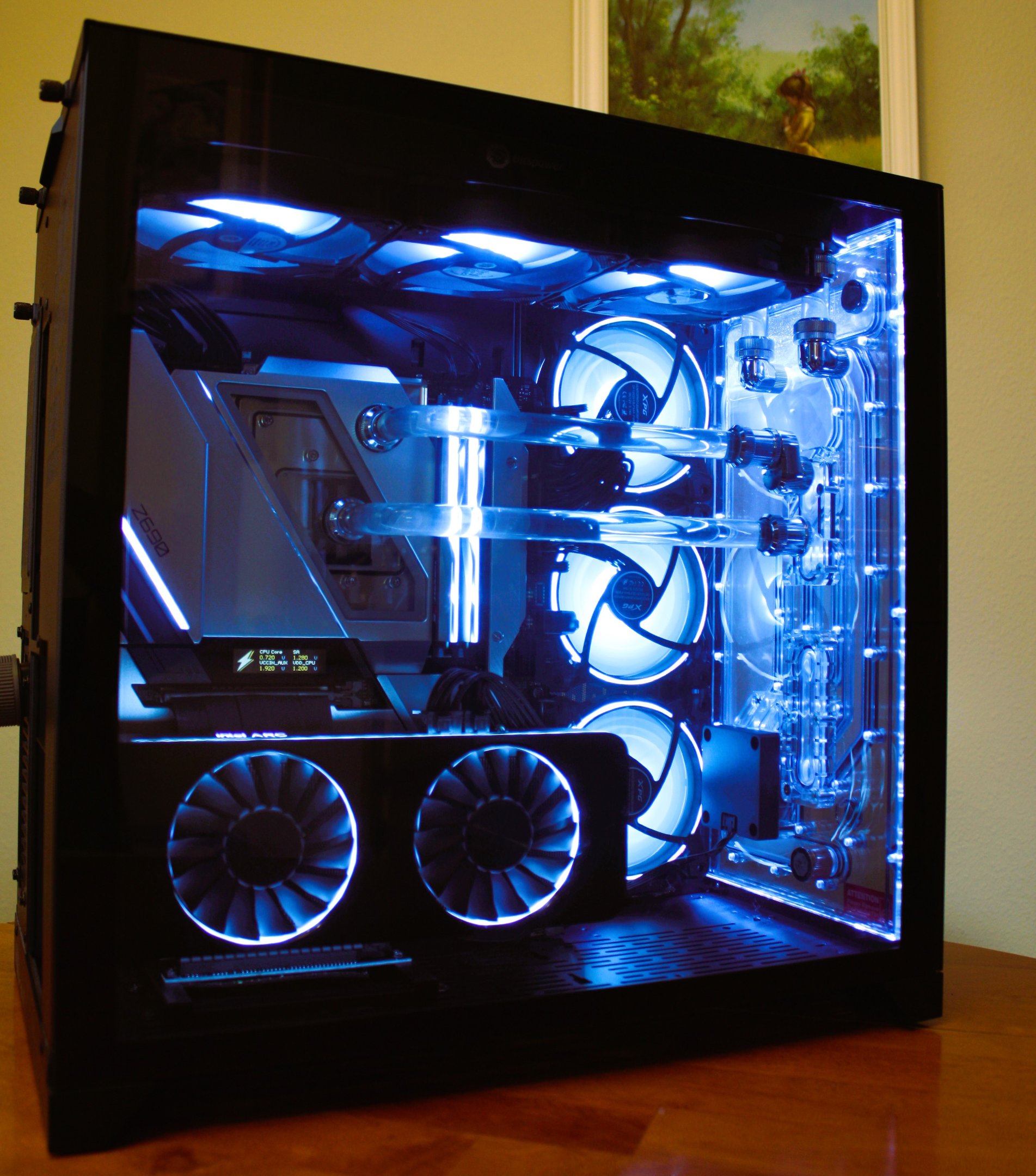
Thanks for getting back to me! The system is built and OPNsense is installed on a little ITX 9900K. I have an Intel 10g NIC for the device too. I think it's total overkill but hopefully, it should run for ages and not give me any problems. I am set up with Comcast DSL at my house. It's rated for about 600Mbps down and 120Mbps up. It's not great but it's what I can get in my area and the price is nice at $55 per month. I don't like the Comcast router/modem even though it's high-performance and free. It's WiFi6 and has never failed once, but it broadcasts the xfinitiywifi signal for all users to piggyback on my network, which is the real reason I want to turn it into a bridge. As for my network requirements, it's pretty simple. I don't need a VPN or anything like that. However, my work laptop is quite aggressive and talks to everything on my network. I was thinking about setting up a VLAN so my work laptop is completely isolated from my home network. I guess I would need to buy a managed switch for that?? Right now I setup a guest account on my WiFi and I connect my laptop to that. I think it's fairly well isolated but that laptop has fangs
-
Hey Guys! I've used consumer-grade routers for the last 20 years and I'm just now diving into this madness I decided to go with OPNsense. It looks like they provide many more updates than pfSense. I built my first router but haven't given it internet yet. I'm going to put my Comcast modem/router combo in bridge mode and run this bad boy as the DHCP host. Any tips or advice?

-
I'm drinking the Kool-Aid myself. My 3090 died playing Cyberpunk so I decided to pick up the A770 and check it out. Obviously it's not a contender for the top Nvidia cards, but it doesn't pretend to be either. I appreciate the value of this card right now but I really love that fact that it's getting noticeably faster every few weeks. I have big plans in store for overclocking and I just picked up a second A770 so I can brutalize one and let it ride the lightning
-
The ARC card looks amazing for the price and it's just the start. I am excited about this GPU and I am looking to grab one as soon as it's available again. Anyone out there have one?
-
Hey keyboard nuts! My wife is about to take a hammer to my current mechanical keyboard because of the late night typing. I need a recommendation of a silent mechanical keyboard, something similar or quieter than a rubber dome one. As for the budget I'd like to stay in the $75 range if possible...
-
Source: https://www.teamgroupinc.com/en/news/ins.php?index_id=150 Team Group has a new mask out, what do you guys think, would you wear it?
-
Hey Guys! I have been using my smartphone for review pictures, but I am continually fighting it and I want to try something new. I really don't know anything about cameras, but I want to try out a simple pint and shoot. I have been looking at cameras on eBay and I was just going to randomly grab something around the $100 price range, but thought it would be a good idea to reach out first. I was looking at the Sony DSC-W800, it seems like a good piece of hardware for the price. I am looking for something that takes amazing pictures (mostly macro), is easy to use even for a complete noob, and is also cheap AF....that's all ? Any help for this noob? Want to trade me a camera for some computer hardware?
-
Team Group has as a huge selection of innovative RGB incorporated products, and on September 22 their product line is getting even bigger. Full news article: https://www.teamgroupinc.com/en/news/ins.php?index_id=142&fbclid=IwAR0WBrHyi2-o2pVNnLFDegl3D6HMXa4JacndGoPUQYlLXCNX5TL1AHzxuK8
-
That's exactly right! I have also seen cards with damaged PLL, 5V, and 3.3V rails...all of those broken voltage regulators could be replaced with this device. It has lots of applications outside of extreme overclocking! Thank you! And yes...my wife would say the exact same thing...with a strong eye-roll tossed in for good measure
-
Elmor recently started taking orders for the AMPLE 20A power card. It’s a simple little single-phase VRM that can be used to replace a broken VRM or simply overcome that pesky OCP/OVP. The most common potential usage would be for a GPU memory rail. However, with an output voltage from 1.0-3.4 V it could be used for many different applications. I obtained a test sample of this new device and I intend to put it to the ultimate test. I have an RX 580 GPU with a damaged memory voltage rail, but otherwise the GPU is in perfect condition. The plan is to solder on the AMPLE power card and observe the impact on the memory overclocking. I know what the card was capable of before the memory VRM died, so it’s the perfect test case for this little device. So follow along as I put this thing to the test and find out if it’s capable of delivering sufficient power to 8 GB of GDDR5. The AMPLE Device The device ships in an anti-static bag with the 6-pin connector added in as an accessory. This gives you the flexibility to power up the AMPLE from any qualifying voltage source you desire. Product Specification Output voltage adjustable 1.0-3.4 V using the on-board potentiometer (range can be increased by adding your own potentiometer) Nominal input voltage 12 V (functional from 4.5 V up to 16 V) Max output current 20 A (thermally limited). Active cooling may be required to achieve high output current. Efficiency at max output 91.5% (3.4 V, 20 A, 750 KHz) Switching frequency selectable between 300 KHz and 750 KHz OVP (+20%), OCP (24A) and OTP (Tj = 150*C) Output voltage can be monitored and adjusted using the EVC2 VMOD1-header Ships with a PCIE 6-pin power connector which can be soldered on by the user Switch 1 OFF = 750 KHz switching frequency Switch 1 ON = 300 KHz switching frequency Switch 2 OFF = PSM = Power Saving Mode, higher ripple but lower loss at low loads Switch 2 ON = CCM = Constant Conduction Mode. The PMIC is always regulating to the best of its ability, for the tightest possible voltage regulation. In some cases, for example with this project at 3.0V+, that will create a high loss in no-load or low-load situations. Source Credit: elmorlabs.com There is one switch on the device which acts as a mode selector. There are a total of 4 different combinations you can set, which change the output delivery settings. For controlling the voltage there are multiple different methods you can choose from. To make things simple, there is a potentiometer on the power card for direct control. For more advanced control, you have the ability to integrate the device with an EVC2 module using the vmod connection. Mounting the Power Card Before you just hastily solder on the AMPLE device, you should take the time to power it on and make sure it works. I would suggest powering it up and setting the desired voltage before you attempt to solder it on a GPU. The underside of the AMPLE has power and ground planes. In my particular case I won't need these connections so I decided to insulate them with a few layers of Kapton tape. This is an unnecessary step, but in my case there were a few components on the card which were extremely close to shorting on the AMPLE device. I chose to mount mine with 0.8 mm copper plate. I kept the plane-to-plane distance as short as possible. Furthermore, I always prefer to make my ground connections on the front of the card after where the main connection is. In the picture below you can see both ground connections come after the memory plan connection. In my testing this provides the best realized MHz whether it be core or memory external VRM replacement. Test Setup The overall goal is to compare stock PCB memory overclocking with AMPLE power memory overclocking. To make the test consistent, I will use the same load voltage for both test conditions. The test methodology is to overclock memory and record the passable frequency in Fire Strike GT1. I will start at 2280 MHz, increase +10 MHz until it becomes unstable PowerColor RX580 8GB Golden Sample Z490 test platform AMPLE VRM on memory rail Memory IC: Micron D9VVR 1625 MHz strap timings copied to 2000 MHz strap (Most efficient timings possible without diminishing returns on frequency) In order to get a realistic look at the voltage response of the device, I have placed voltage test points (TP1-3) at various distances away from the main inductor. During the load tests, I will also be conducting thermal tests of the mosfet heatsink. Ambient temperature for all tests around 24c The voltage read points are as follows: TP1 = AMPLE power voltage at C10 cap TP2 = GPU plane voltage at solder connection TP3 = Memory IC voltage at MLCC cap on back of card, at least 100mm distance from AMPLE Vout solder connection Test Results Voltage droop is the enemy of external VRM mods. It’s important to know exactly where the voltage droop occurs because it can narrow down the cause. The voltage test point results indicate that the droop is not caused by the solder connection. The voltage droop is present at the C10 capacitor so therefore it’s coming directly from the AMPLE VRM. This makes me happy because the solder connection is relatively perfect, but it’s mildly concerning to see the AMPLE being stressed under load. Regardless of any droop, the card was still able to pass FS GT1 test at the highest possible memory frequency. There is effectively no difference between the stock VRM and the AMPLE VRM for this test application. The temperature reached a peak at the end of GT2 and was still climbing. With the Fire Strike test, GT3 is CPU based so it had a cooldown period. The max temp of around 50c seems reasonable but further testing may be needed. Sustained loads of 1hr might show a different result. SW1 Test results proved inconclusive. Disregarding experimental error, there was effectively no difference in the realized MHz or voltage response. Conclusion Overall I am extremely pleased with this little device. It performed exceptionally well and the end result is that I was able to achieve the same overclocking performance as the stock PCB. The AMPLE single-phase power card has been validated for benchmarking purposes. In terms of the switch options, my expectation was that CCM mode with 750 KHz would be the optimal configuration. The switch test results showed that the various combinations didn't have any noticeable effect on realized Mhz or voltage response. The 10 mV voltage droop is a mild concern because it’s coming directly from the AMPLE, however, it did not affect the overall overclocking result. With a price tag of just $20,, it’s an absolute must-have tool for extreme overclockers. My RX580 is the perfect use case. The card was effectively dead and useless, but the mighty little AMPLE device brought it back to life and it still holds gold in TIme Spy. Even if the price was tripled, I would still recommend it because of its potential value. This was just my first test, stay tuned for more tests to come.
-
Windows 10 2004 (2020 May Update) Now Available
mllrkllr88 replied to ENTERPRISE's topic in Operating Systems
Wow, really nice! This is a great tool and very useful, thank you! I am often testing different versions of W10 for benchmark efficiency, this makes it nice and easy to grab any one I want. -
Ok guys, anyone out there able to help me setup and optimize Threadripper 3970X? It looks like some people are getting it up to 1 million PPD...which seems like alot for a CPU?? I did a bit of googling and it seems there are some tweaks that need to happen to get the max out of this thing. I read some stuff about 'slot' settings for core/thread count but I am totally clueless. Also, can anyone give me a really quick summary of how this scales with overclocking? For instance, how much system memory does it use and what the score increase? Overclocking CPU? Mem? I've been in the professional XOC world for some years now but never touched folding until yesterday...I know nothing.
-
Good catch, I let it munch last night then saw this a few minutes ago. I swapped teams and now it's working again
-
I have never folded a day in my life, but I have a rig I can setup and try this out I might need some help from the folding pro's...
-
Cryengine Neon Noir Benchmark, Submit Your Scores !
mllrkllr88 replied to mllrkllr88's topic in Benchmarking General
All basic mode... 1920x1080 with 60Hz The bench automatically loaded in a window, which I have no clue what size that is. I did nothing but install and run on a dirty v1909 W10 install. -
Cryengine Neon Noir Benchmark, Submit Your Scores !
mllrkllr88 replied to mllrkllr88's topic in Benchmarking General
Bone stock run with absolutely ZERO tweaks or OS optimizations.... This is just a simple 9900k on Z170 with XMP memory and a stock 2080Ti KP. It looks like the score is higher than it should be, bummer this bench is so inconstant. -
Cryengine Neon Noir Benchmark, Submit Your Scores !
mllrkllr88 replied to mllrkllr88's topic in Benchmarking General
I am getting setup to play with this bench again. Looking forward to helping out with the testing and seeing if we can figure out the how it scales. My biggest complaint is that this bench cannot be run in offline mode, and requires a huge download. -
Cryengine Neon Noir Benchmark, Submit Your Scores !
mllrkllr88 replied to mllrkllr88's topic in Benchmarking General
Oh that's really odd. I only did a quick run and I don't remember what my config was. I will have to play more and nail down how this bench works. -
Cryengine Neon Noir Benchmark, Submit Your Scores !
mllrkllr88 replied to mllrkllr88's topic in Benchmarking General
A few things here. Firstly this bench is very inconstant in terms of run-to-run score. Run the bench 5 times and you will see a big variange. I saw a big gain from disabling SMT, so that's something you can try. -
Cryengine Neon Noir Benchmark, Submit Your Scores !
mllrkllr88 replied to mllrkllr88's topic in Benchmarking General
I ran a quick one using RhreadRipper and stock card, so I am guessing the score sucks... We need more runs to compare to -
5.1GHz i9-10900K processor spotted with 10 cores and 20 threads
mllrkllr88 replied to Andrew's topic in Rumour Mill
The madness begins! I am excited for the new platform and cant wait to start playing with it. -
ended The EHW & InWin Monthly Giveaway!
mllrkllr88 replied to ENTERPRISE's topic in Promotions & Contests
It looks like the winner has been announced, congrats! -
ended The EHW & InWin Monthly Giveaway!
mllrkllr88 replied to ENTERPRISE's topic in Promotions & Contests
December is almost done, good luck everyone!! -
ended The EHW & InWin Monthly Giveaway!
mllrkllr88 replied to ENTERPRISE's topic in Promotions & Contests
My 2080Ti desperately needs that PSU for so it can be a dedicated GPU PSU for LN2 GPU sessions. If I win, I will certainly post pictures of it in use My contest submission 1. Yes please, Im In 2. Share this giveaway thread on your Facebook or Twitter 3. Follow EHW Facebook. 4. Follow EHW Twitter. 5. Follow InWin Facebook. 6. Follow InWin Instagram. 7.Create a thread with useful information such as a guide/how to in an appropriate section of The Forums I present my GPU volt-mod guide: https://extremehw.net/forum/modifica...-voltmod-guide